
Use Tubes? Then get the uTracerNXT Tube Tester Kit to check out those tubes. See how easy it is to build in this close-up build review?
The uTracerNXT Tube Tester Kit Inside and Out Review 2026
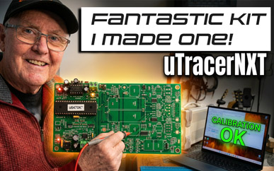
The perfect solution for tube testing - The uTracerNXT
Introduction and Preamble
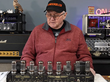
So if you're like me, you might have a tube amplifier, or a hi-fi amplifier or something else that uses tubes or valves as they are also called. And all that's great. As you can see on that picture above, That amp is a Mesa Boogie Triple Rectifier rev D, and that has a huge array of tubes . Now if even just one tube is questionable, that amp will simply not give you as a guitarist what you would think it could. After all the tubes are everything.
And as well as each tube actually working, there's the question of 'matched' tubes? What does that even mean? Well, those tubes often operate in a 'push-pull' design and having tubes that are matched helps make the amplifier operate better. Miss-matched tubes can make the amplifier more difficult to 'bias' the tubes and when the biasing is wrong or out of alignment because of the miss-matched tubes then the amp can sound very 'cold' or equally create operational problems where the tubes simply don't last long.
In any case, the reality is, that if you don't have the right gear to test and check each and every tube in the amplifier then really you could be walking a tightrope. I always mention when I bought a Diezel Hagen guitar amp and it was used but a backup. It came with particular tubes installed (JJ) and I started to play the amp in the studio and in a very short time one of those JJ tubes lit up like a light bulb - and I mean super bright! I quickly turned off the amp (I was just feet away) and frankly I saved the amplifier from a sure catastrophe from that failure. A blown tube like that can be very costly if it zap's your guitar amp.
But like you? I had no way to test the tubes myself. But I had seen one being sold as a kit on the internet - a uTracer 3 but did not buy it. Later the company at dos4ever.com released a new design called the uTracerNXT as a kit so I decided to dive in and buy it - and 'have a go' so to speak.
What's A uTracerNXT?
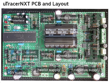
As you can see from that image above, the kit comprises of everything you need to make that PCB. And the manual is brilliant! All you have to do really is practice soldering for a while if you can't solder, be able to read the manual, and trust me you CAN make a really good tube tester that has the advantage of being 'up to date' as compared those old 1950's and 1960's tube testers that you sometimes see on eBay. The problem with those old testers is the unreliability (and the cost!) etc. but with the uTracerNXT its all modern.
So What Will I Need?
To be honest with you, you do NOT have to be an expert and you don't have to have loads of gear. When I bought this kit I basically had a few tools including:
- A power supply that can be adjusted to around 20 volts - or a 19.5 volt power supply used for the project
- Soldering iron (mine controlled the temperature of the tip)
- A general meter that can measure volts, amps, Ohms' resistance etc.
- A silicone mat so I could solder easily without damaging the table
- De-solder tool (cheap) in case I made a mistake
- De-solder braid and solder (I used lead based solder)
The obvious pliers, snout nosed pliers and even a magnifying glass all came in handy because some of the components are a bit little. And that was it. I have to say that I did have a combined meter and scope but to be honest I never used the scope at all.
Tell me all about the uTracerNXT Kit
The uTracerNXT is available as a kit and there is much information on their website but don't let the initial complexity put you off - the kit really is not that difficult to build and the designer Ronald is always there to advise and help!
The Manual
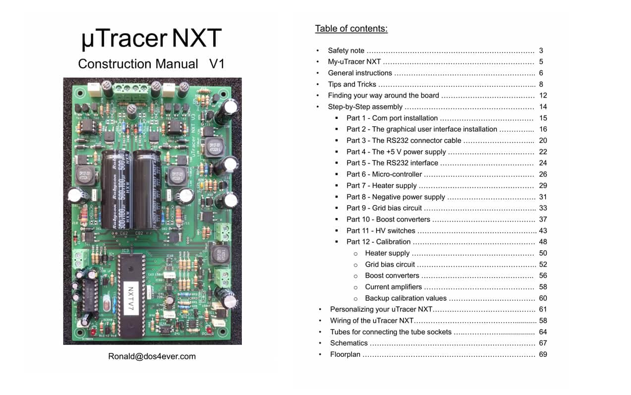
The included manual will take you right through the build from start to finish. Honestly the manual could not have been better laid out, it covers everything from safety issues, though getting started etc. and breaks down each step of the building of the tube tester in to simple sections (as you will soon see from my build) and you can test each and every section as you go, so it all becomes so easy and you'll find any errors assuming you have any.
I can't really put in writing just how good that manual really is, but even as a novice with a bit of due diligence listen its not really that hard.
Building The Kit As A Guitarist
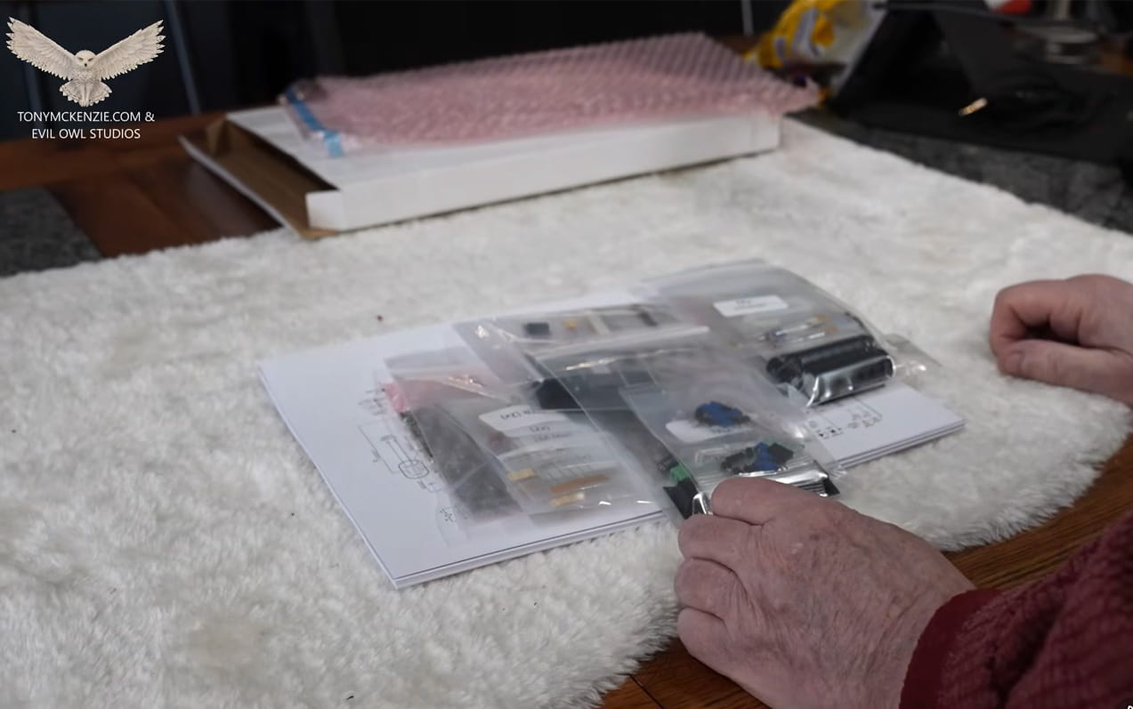
OK after getting the parts out of the package you will see components neatly sectioned off in little plastic bags and the included manual. The parts bags tell you exactly what's inside the bag. Now if you're not that electrically minded and don't know a 100 watt resistor from a 10,000 watt resistor then calm down! Its all written on the particular bag and you just grab the bag that you need as you fit the part. So this is not really difficult especially if you take your time 'step by step' and you'll end up with a great tube tester.
Tools
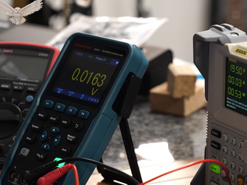
Now I don't show all the tools I have in the above picture, but honestly I have a couple of meters for measuring amps and volts and maybe Ohms, a power supply (but mine is a fancy one and yours does not have to be like mine, and a soldering iron and a few other bits as I mentioned earlier.
Building The uTracerNXT Kit
The manual takes you though the whole build in easy small steps so that you don't have to do it all in one go - it's not a race!
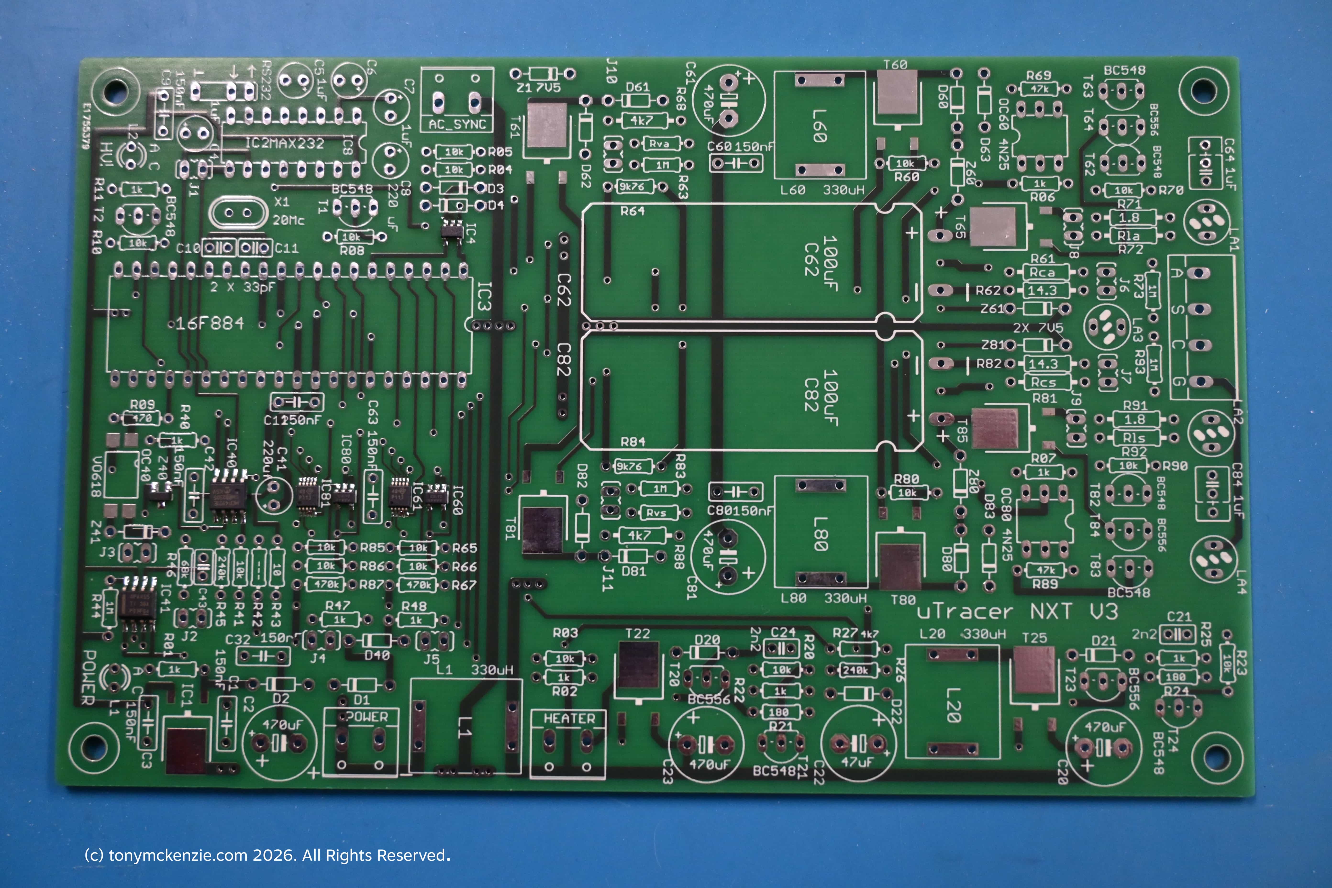
As you will see if you click the above image, the PCB itself is marked out where everything will fit! It's almost a jigsaw puzzle :) slightly more complex, but it is not beyond anyone who can solder and has a few tools. So I proceeded to fit the components to the board and followed the manual - well almost!
I should have worked (as you should) from step 1, then 2, and 3 but I actually started at part 4 just because I could and I went back later to complete part 1, 2 and 3. Assume I completed those as you should!
Part 4 My Only Problem
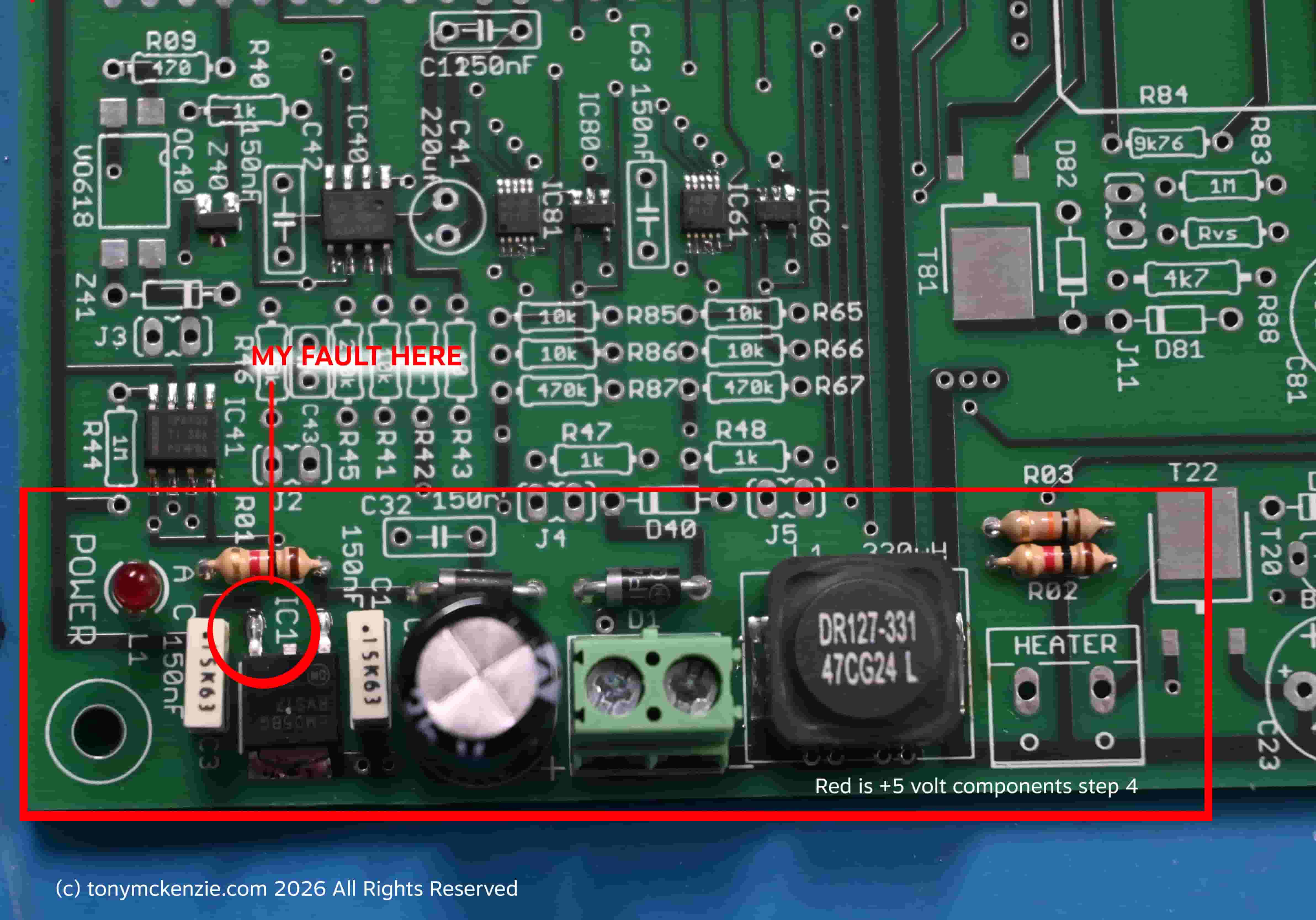
When you complete a stage you have to check it out and then test each stage - and part 4 was the power supply +5 volt section. Open the larger picture and you can see the +5 Volt components, and you will see IC1 with a red circle around it. When I soldered that to the board the left leg was not quite perfect soldered and this created a problem when I tested the +5 volt from pin 32 on the PCB IC3 location yielded nothing, but should have been a +5 Volts! A quick re-solder of that left pin on IC1 and it all worked!
Part 5 - The RS-232 Interface
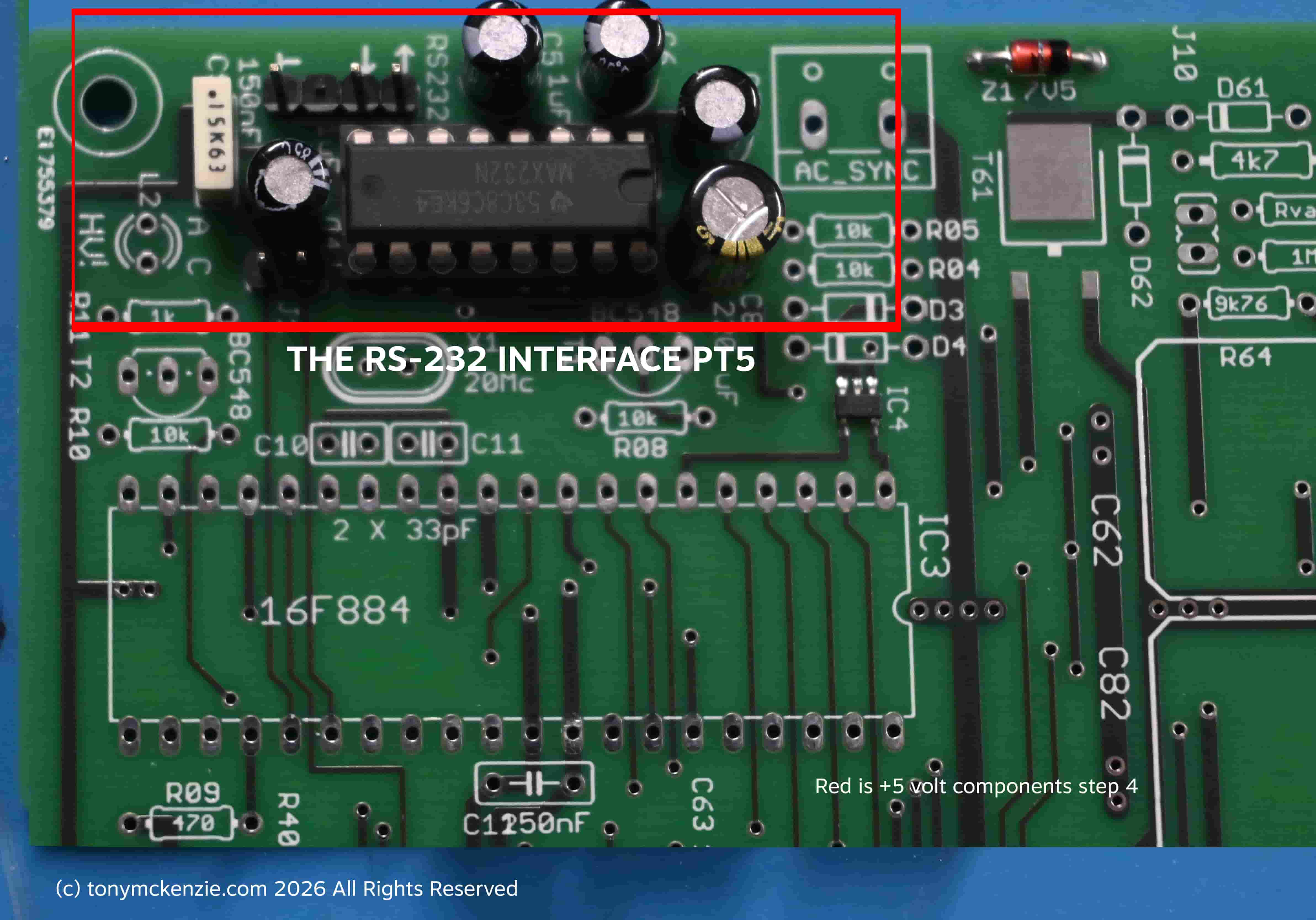
Completing the part 5 of the build is relatively simple and just follow the instructions in that manual. After this step I went back and did step 1, 2 and 3 and because I had completed this step 5 I found that easier for me! You may not necessarily find that so I recommend you stick to the manual.
For step 1, 2 and three I used a Windows laptop and a specific cable that worked for me. I had experience with this cable in other projects at work so I used that and it worked perfectly so its a recommended cable.
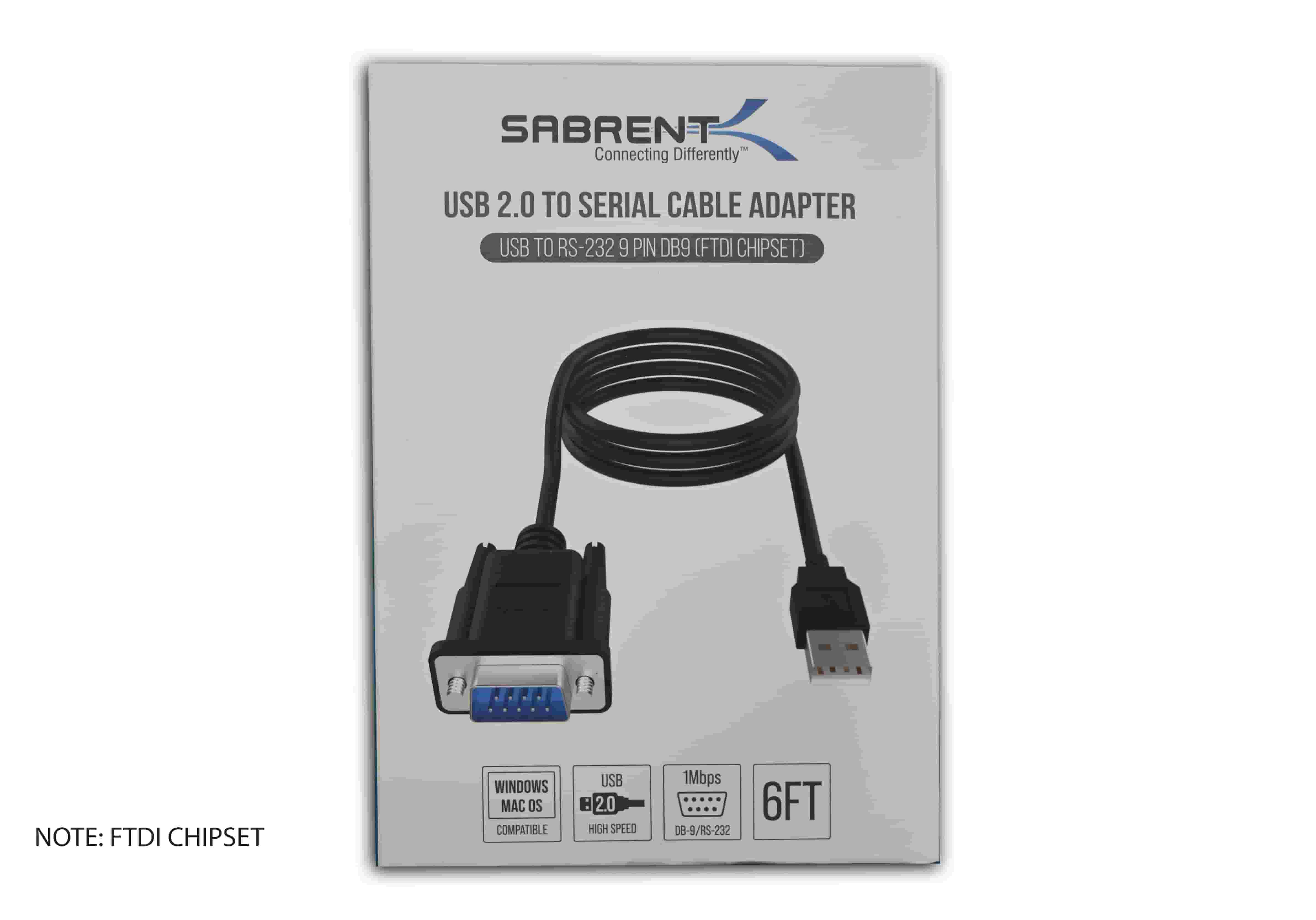
Above is a close up of the packaging for the FTDI cable I purchased. It should work on almost any platform really and Microsoft already had the drivers in Windows 11 when I plugged it all in at the time to test the interface. This cable was bought from Amazon UK. Recommended!
Make up the cable as in the manual in page 20 and 21 and plug it all in.
Install the Software uTracer-NXT-Gui
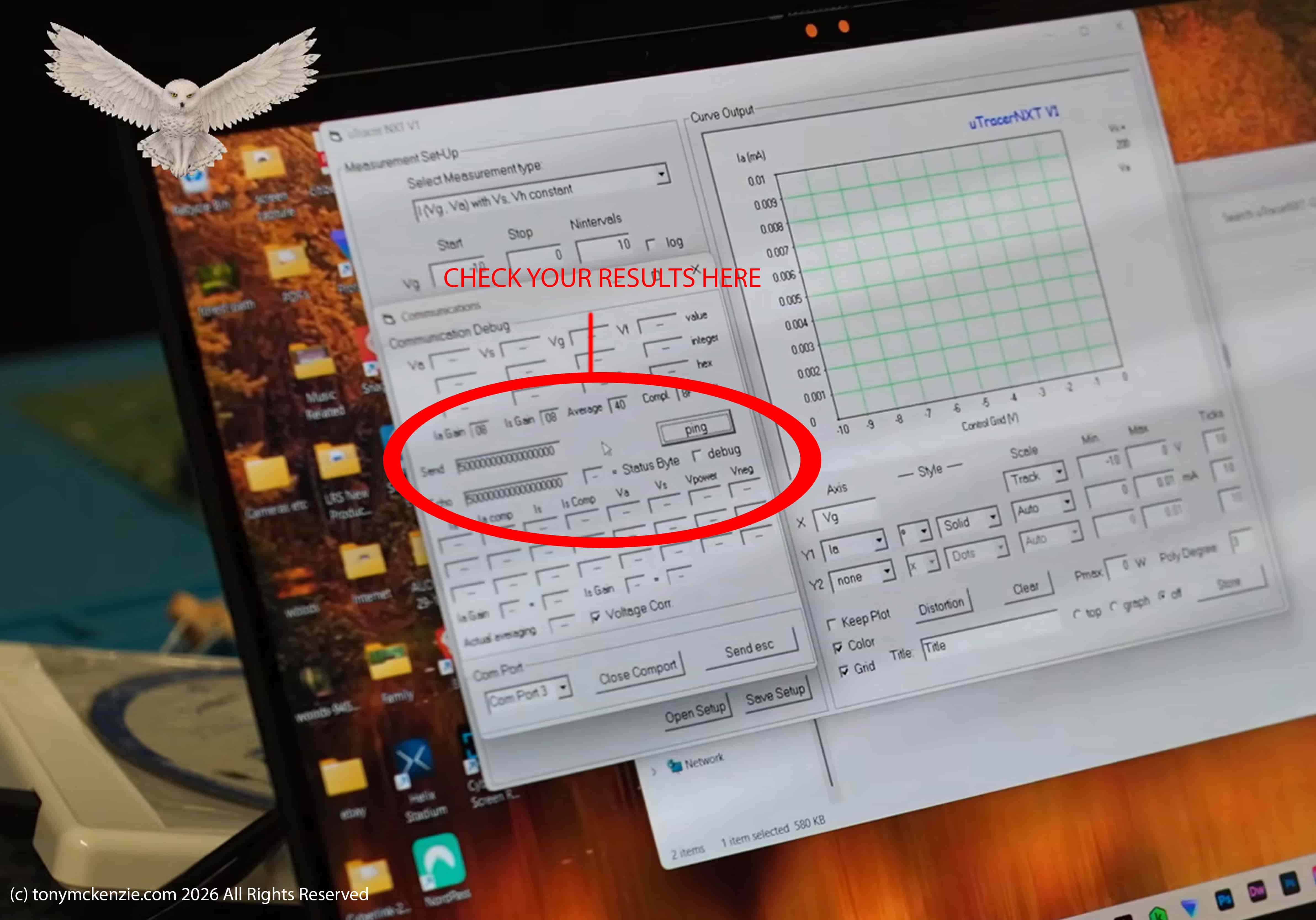
Download the software and install it! Follow the instructions and its no problem. My software installed as 'com 3'. Basically once its installed run the software, choose 'debug', choose your com port, then hit the 'ping' button, Mine worked fine as you can see. The thrown up error that occurs after the test is normal!
Part 6 - Installing The Micro Controller
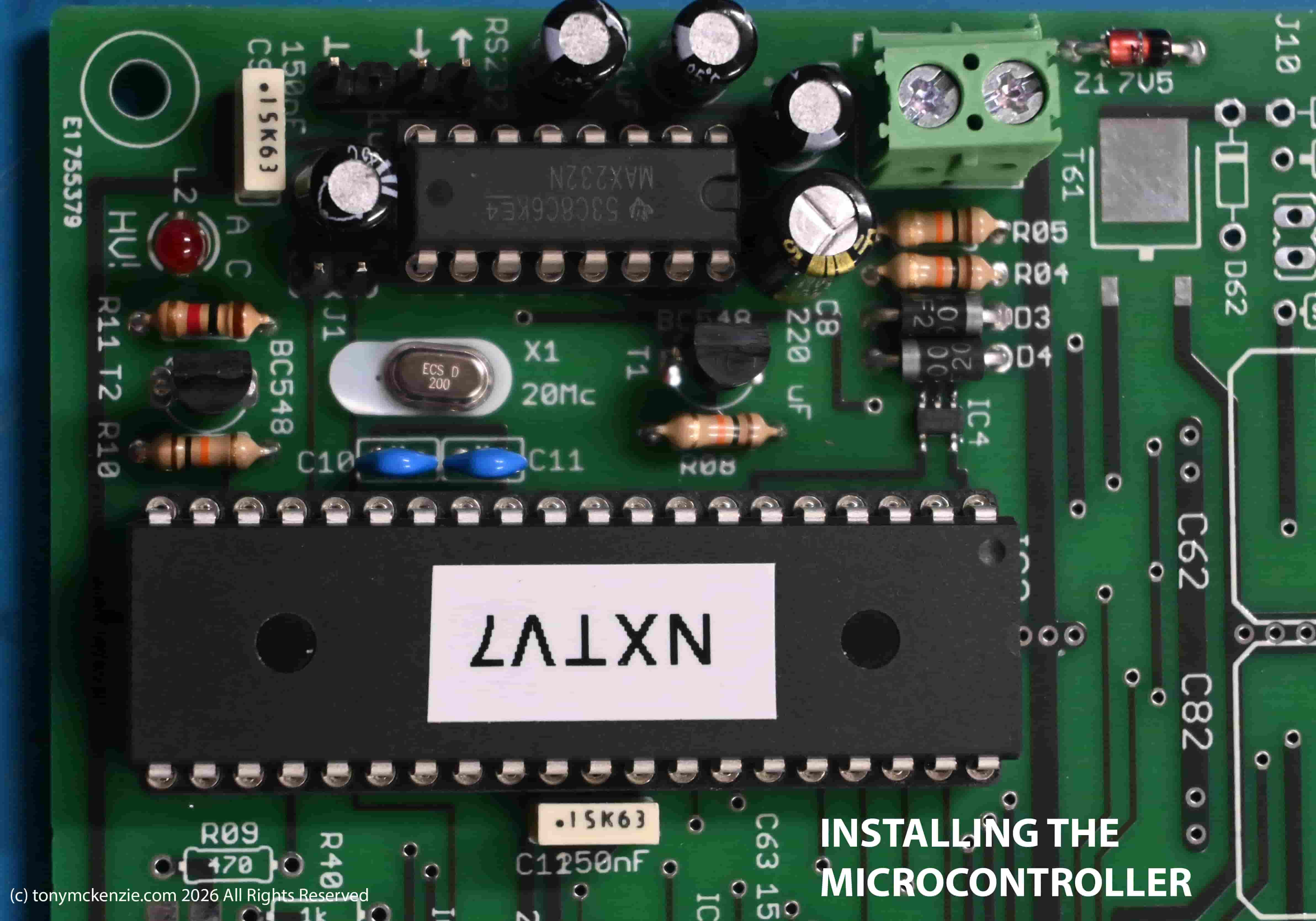
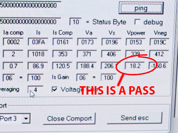
Install the parts as specified on page 26 of the manual and as shown above. And on page 27 there's a 'part B' that you have to do. Basically you have to test out the micro controller section you just fitted. I found all of this pretty easy to do myself. The components were not difficult (but always check twice with those before soldering) and the testing was easy enough.
For the test set up the board with the right voltage in and connected serial cable etc. and you should have as shown above that voltage of 18.2 or thereabouts and its a pass.
Part 7 - Heater Supply
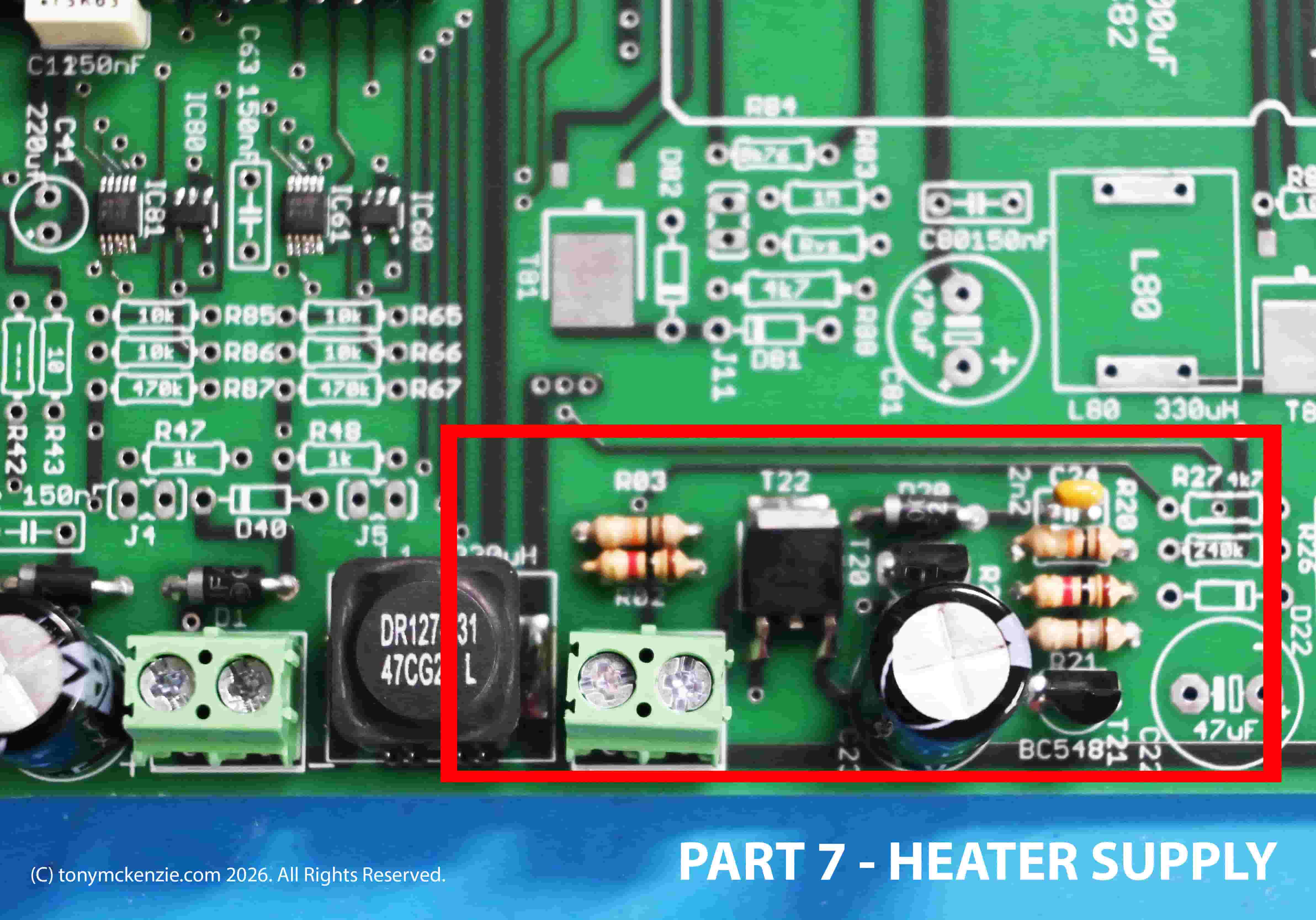
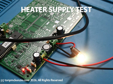
Install the parts as I did as you see above - its all on page 30 of the manual (remember that the page might change in the manual you have! Once you have completed that its time for the test. You will notice in the testing section that you need two regular bulbs - buy what they say or as near as possible. Follow the instructions for the setup and test and those bulbs should (one at a time) glow and then fade. If they do that (its controlled form the software) then you have passed the test. Mine passed first go.
Part 8 - Negative PS Construction
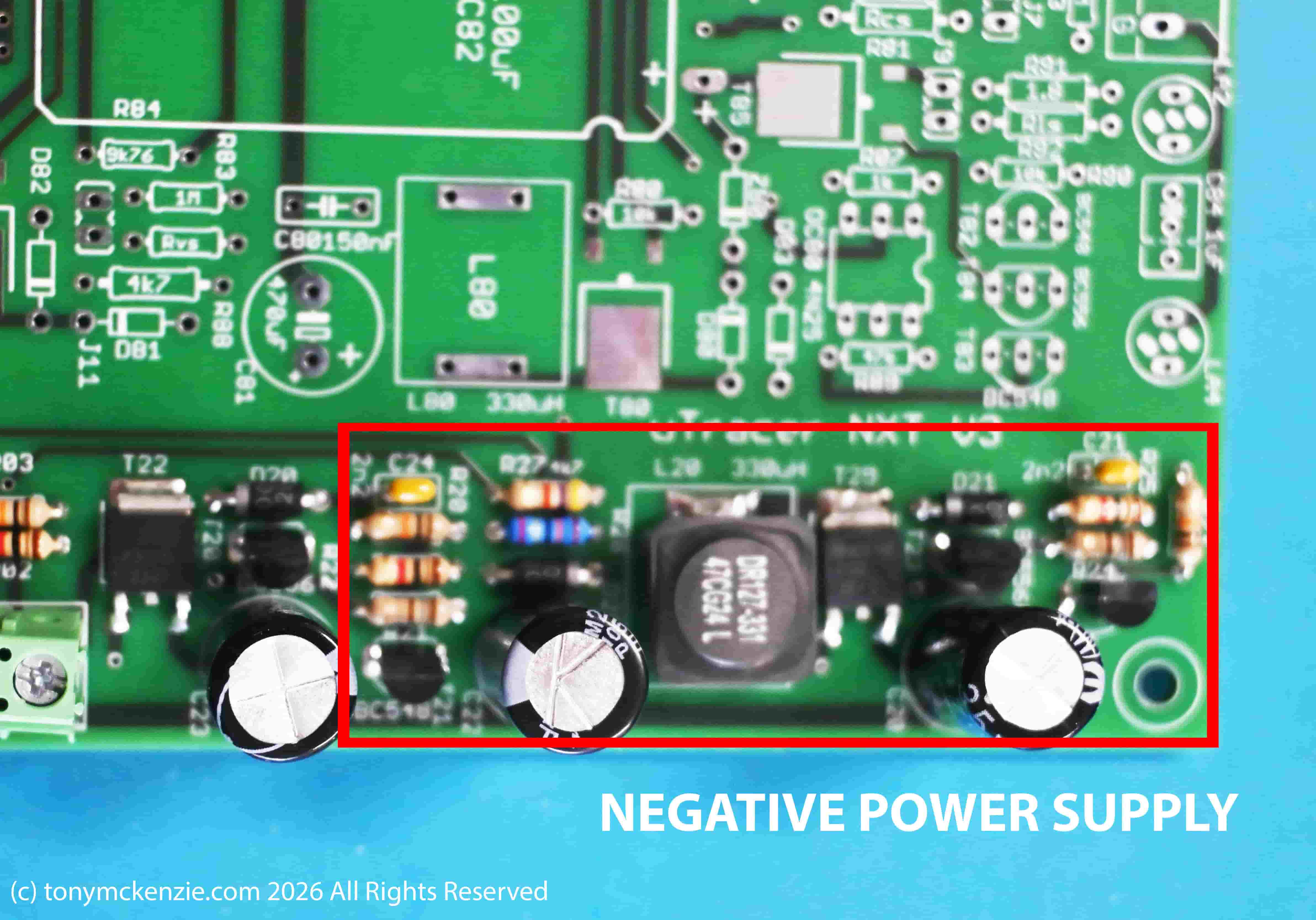
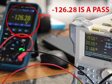
Same old thing, fit the parts as shown in the manual - not difficult at all. Page 32 of the manual runs through the testing of the negative power supply. Set the current limit correctly and carry out the test. My results were -126.28 volts as that image above shows. It's a pass.
Conclusions so Far
Well the kit so far other than that simple error I made is great...
If you are new to this type of building electronics etc. and you are this far down the road of assembly, you should be proud of yourself. Of course an old hand will walk it all, but that's easy for them and harder for the novice that has to build up the experience and let's face it, its simple if you are successful and less so if you failed. There's more to complete, but don't break out a sweat, take your time and enjoy the building of this tube tester.
I love the way that everything is included (except those two bulbs!) and the manual honestly is a masterpiece. It left nothing to guess and at no time have I been 'stuck' as what to do next and that's a sign of a great kit. So let's continue on and get this thing completed.
Part 9 - The Grid Bias Circuit
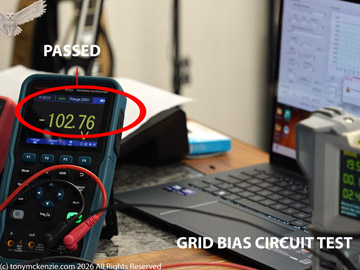
Its not really easy for me to show the measuring of this test but I do have a image to share (its not perfect). Set everything up exactly as it says in the test and the results should be something like mine above.
Part 10 - Boost Converter
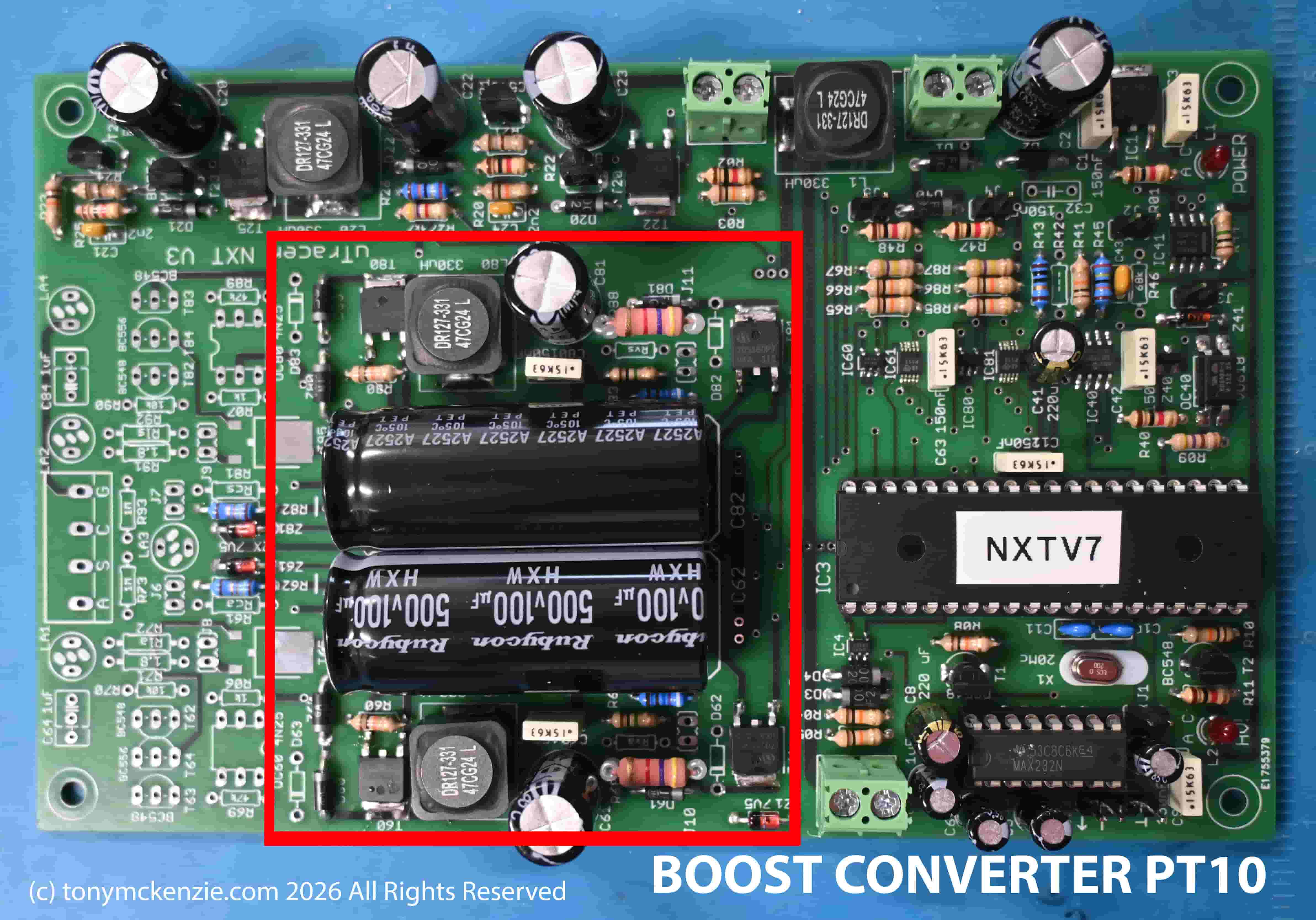
Above is the board after I fitted the boost converter parts etc. and click it for a big view. But it does have many steps in the testing procedure. There are two parts to this section and this part was test one - I achieved 195 Volts from my part one test. I did this test with just one volt meter as described in the manual.
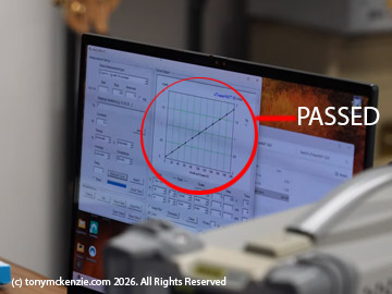
Test two (page 42 of the manual) involves testing the current amplifiers. This second test (you must follow the procedure exactly) shows a graph on the software and the example in the book is exactly what yours should look like. My graph is similar - and I think that is a pass - check the above test result for part two. Your graph should be the same at the very least.
Part 11 - HV Switches
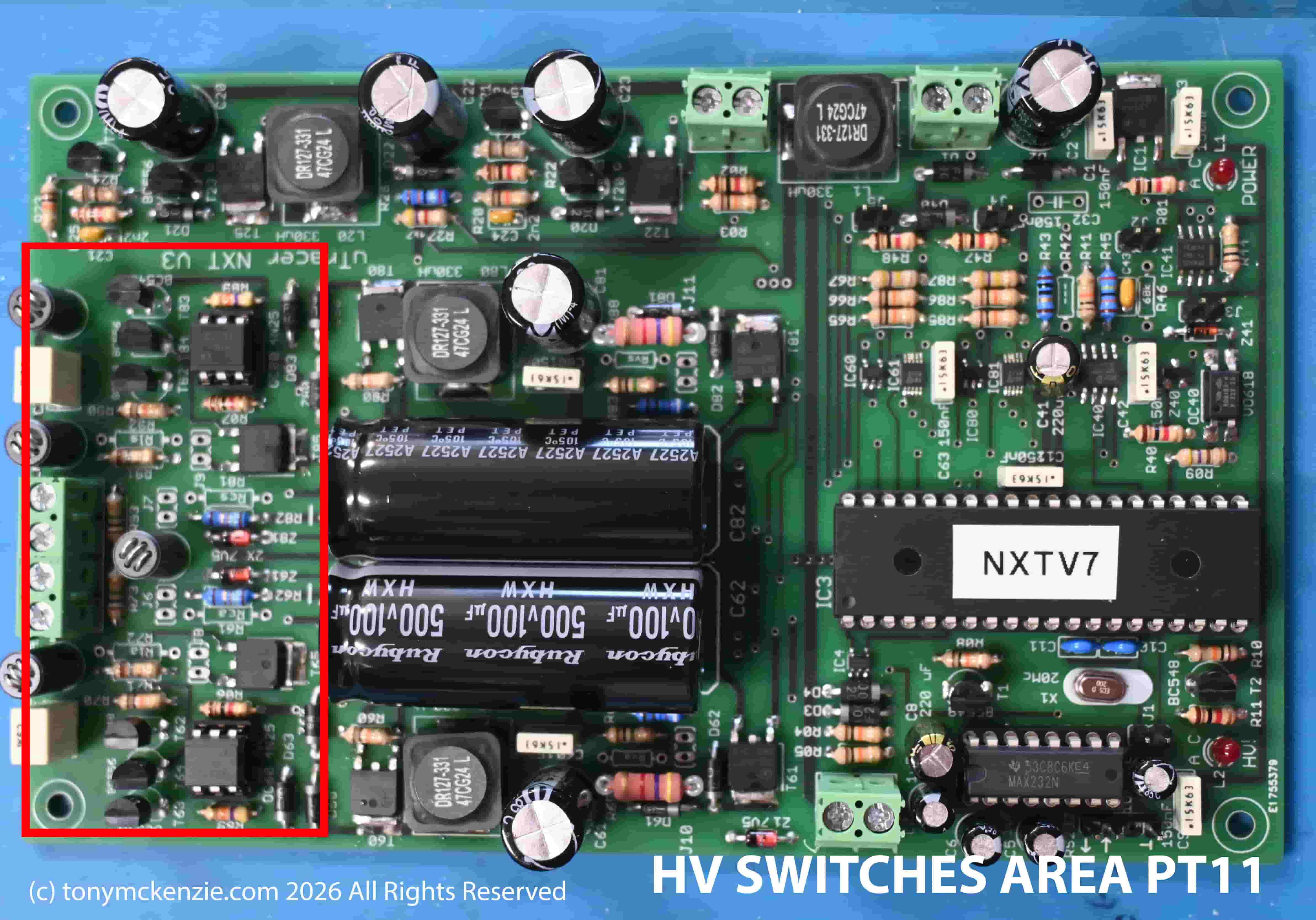
Fit all the components and take your time! We're on the last construction phase of the main board and don't want to get anything wrong at this point. There is a HV switches test and then there's the calibration of the board through multiple steps - there are about eight pages of calibrations to carry out. I completed the HV switches test and it passed.
Just before I leave this section do bear in mind that Ronald did give some spare parts that you can fit - depending on exactly what tubes you will test and the requirements of the uTracerNXT specifications - those parts can modify it a little from the 'normal' setup. I did at this stage cease to carry on fitting bits as options because I'll only do that myself if I need to do it. This really completes the building of the board with its components.
Calibration of the uTracerNXT Main Board
So what about all these calibration tests for the uTracerNXT? What did I find? Was it easy?
Well the calibration is a bit of a journey. I cannot easily sum up all those tests except to say that the calibration is a critical and important aspect of the build. If the calibration is out (even if the board is built right) then you CANNOT achieve the correct results for any tube based on a miss-configured software entity - and really my guess (and it IS a guess) is that really you are calibrating the software, and through each stage, the modified sections (carried out with sliders in the software etc.) all matter greatly. Getting the calibration as perfect as you can I think is essential. Thankfully the manual goes through it all and makes everything add up, even for guys that don't have the experience or have never calibrated anything before.
I do have some images from my calibration phase but to be honest it's likely they won't really be any great use to the reader at this point. I recommend you knuckle down and get through those seven or eight pages to get your board and software calibrated accordingly.
So this completes the board build, install and calibration of that important software and the position is now that the board is ready for installation in to a case, with its specific wiring for what you want to test etc. and the assembly of the case complete. The case assembly will likely be added as a 'part two' and final part of the uTracerNXT project as this written review is very long and not always the best for a webpage to be found by readers.
General Opinion
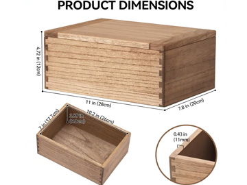
I can tell you what I want to test... EL34, 6L6, KT66, KT77, KT88, 12AX7 and that whole series like 12AT7 etc. and maybe the odd 5851 and that sort of thing, in fact the tubes that are typically in a guitar tube amp, and I might throw in a couple of rectifier tubes (or not depending on how hard that is to do) just so its as complete as I can get the tester. And I have a wooden case assembly:
I could have gone down the road of buying maybe one of those 'Orange Tube Testers Version 2' but having had Version one I decided against that. I did review the orange tester some while back and that's on my YouTube Channel. But to be honest, this tube tester project is firstly cheaper, I will learn far more than just buying a tester, and of course I'll have the great feeling of achievement when it finally works! What's not to like.
I am happy about the boards build quality and calibration tests, and I would rate the build as something a novice can do providing they can read, solder, and have the few tools necessary to complete the work. They also need a computer to run the software and understand how to use the software. The builder will learn some of that software as they test each section. I found the section testing as the build moved forward especially interesting and it stopped me from making a mistake that later I would have trouble in finding on a completed board.
Overall Score
What I would say is this: If I was a competent guy with much experience this kit would have a 10/10 score no doubt. But I am not perfect and don't come from being an electronics engineer. Nigh on everything though was brilliant so far and only one thing stopped me giving the kit a 10 score. And its not a major issue, but from my point of view I think it matters. My overall score is 9/10. The 'lamps' I used part way through the build for heater test I did not have and did not know I needed any until I actually needed them. Then I had to wait and mess around for them to arrive one from Halfords in the UK and the other from Amazon. You might laugh - fancy Tony marking the kit down to a 9 for that... I hear you, but that's all OK until it's YOU building the kit :)
In any event a 9/10 is a brilliant score and in every other respect this kit is entirely recommended so there :)
Warranty?
I'm sure that if there was some problem with component missing or something like that Ronald would help. But having a warranty on a kit frankly in my opinion would certainly be difficult. My guess once you have it going the warranty should be back to the builder... YOU!
Final Thoughts?
This uTracerNXT has been a great project to work on and I have yet again learned much form the projects I have completed in the amplifier and testing area of electronics. So with a relatively low cost for the kit, I can recommend that if you need a tube tester then buy one!
Watch for the final part in due course.
Links:
The Orange Tube Tester V1 Review
If you like my reviews PLEASE Subscribe to my YouTube Channel as its always appreciated.
Thanks for visiting my tonymckenzie.com website, currently I am completing 21 written in depth reviews to bring my website more up to date so the YouTube stuff has to wait a while, It does not sound much of a task to create these reviews but in reality will take me months to complete.
The uTracerNXT in its entirety shown in this review was bought by me personally and there has been no sponsorship in any way. This is a genuine and true review written in my own words reflecting my opinion and experience with the product. Please do visit my YouTube channel and SUBSCRIBE etc. Thanks for visiting this review.
© A B McKenzie 1997-2026. All Rights Reserved. All Trade Marks Acknowledged.